Comparativ example
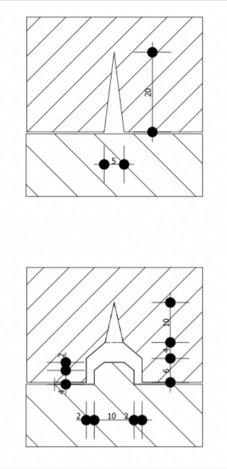
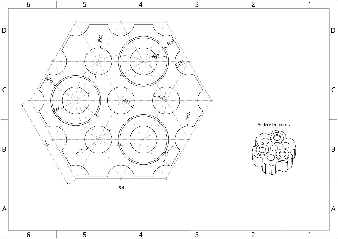
The drawings show a SI-AL chequer brick at the bottom of the regenerator currently used, of hexagonal type, with interax distance of vertical channels of 45 mm - and, therefore, the side of the regular hexagon of the network of 90 mm - and the inner diameter of the vertical channels varies by height between 30 mm at the bottom and 27 mm at the top (average 28.5). In operation, the heat transfer area per cubic meter of structure is approximately 51 sqm/m3, regardless of the height of the chequer brick. At the right side we have a corresponding similar chequer brick, made according to the patent. The height of the two chequer bricks is identical and set at 60 mm to illustrate the importance of this value in the case of new chequer brick (it is inversely proportional to the number of possible horizontal channels per unit volume of the structure).
The data of volumes and surfaces are presented in the comparative table and are based on figures provided by the computerized realization in "3D" of the drawings. It should be noted that the manufacturing values differ from those in operation due to the expansions of the refractory material, so that the exact figures belong to the manufacturing drawings.
Comparative table - example of chequer brick according to the patent
- dimensions at manufacture according to the drawings -
| Chequer brick type | Volume m3 | Leaning surface m2/m3 | Thermal transfer surface m2/m3 |
| Classic "hot" | 0,612 | 0,368 | 51,055 |
| Classic "cold" | 0,598 | 0,345 | 47,19 |
| Modernized "hot" | 0,618 | > 0,411 | > 79,92 |
| Modernized "cold" | 0,604 | > 0,386 | > 73,87 |
Note:
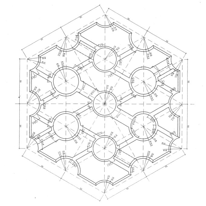
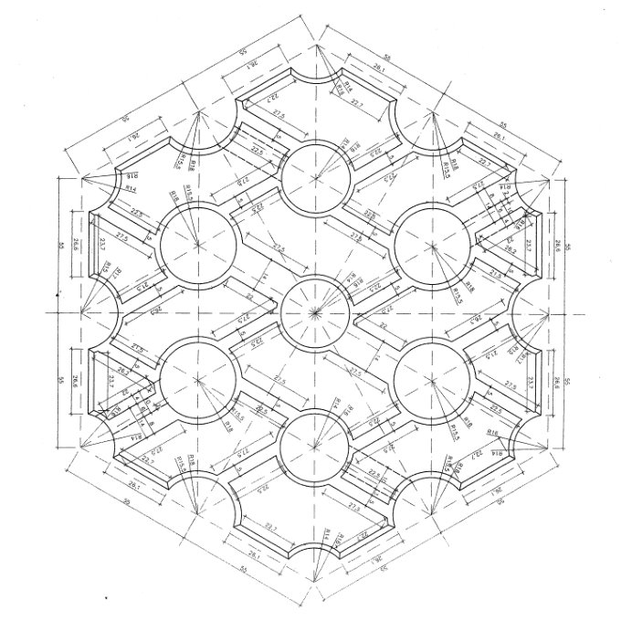
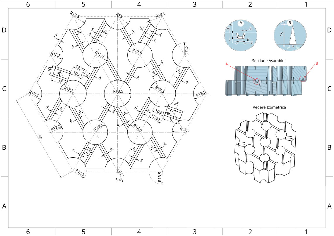
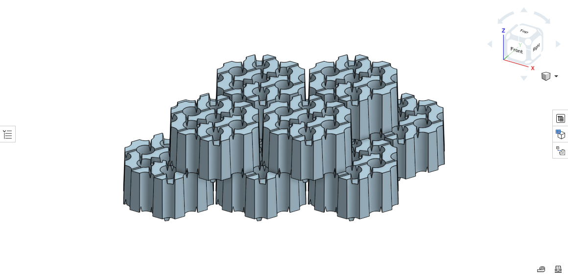
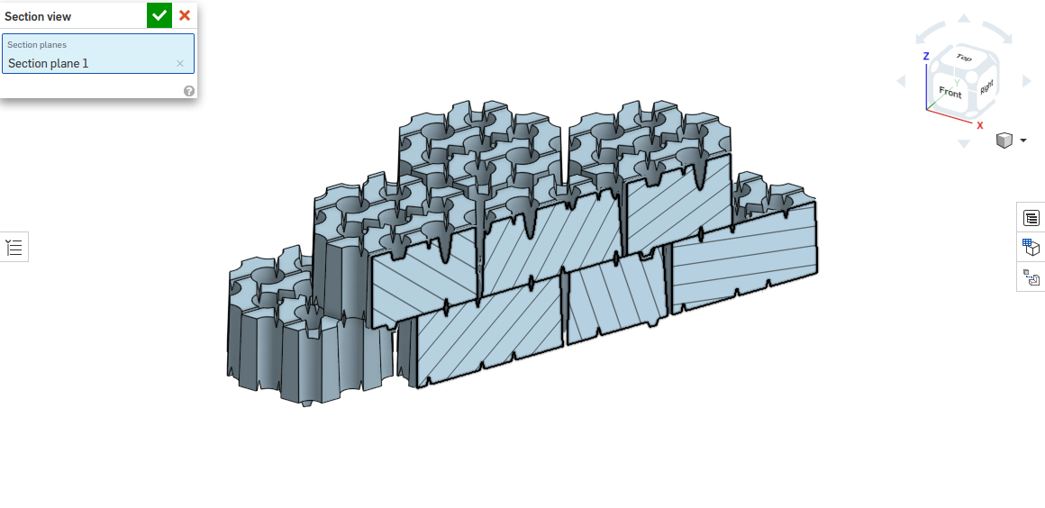
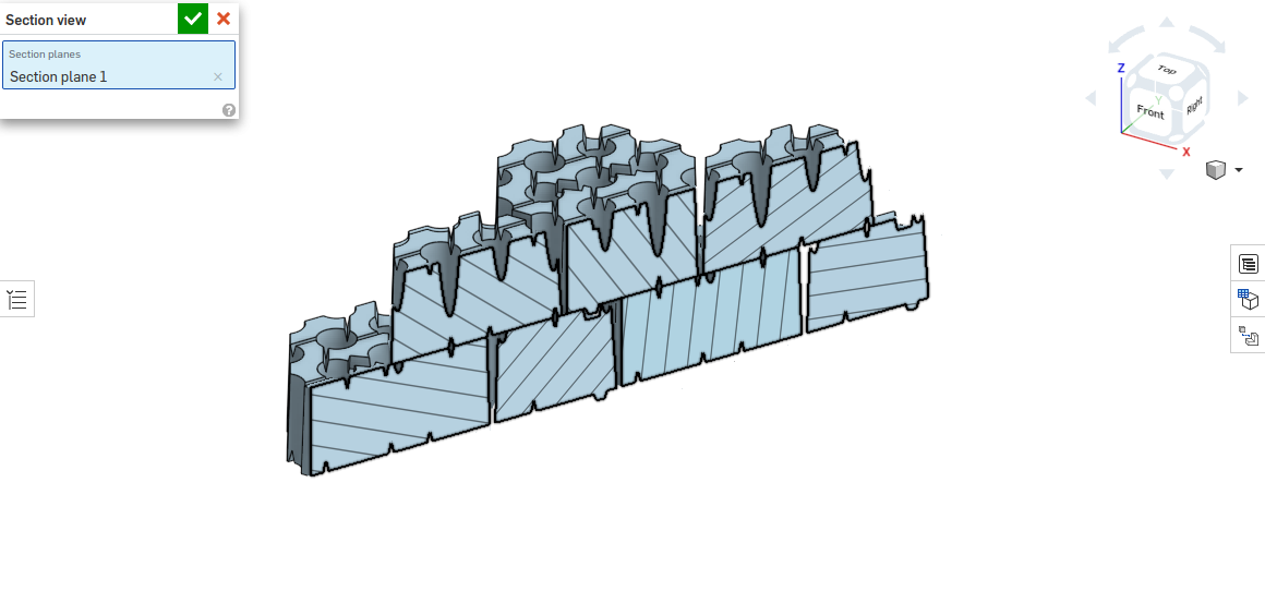
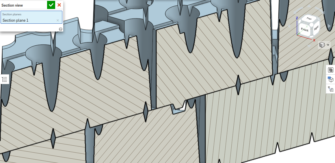
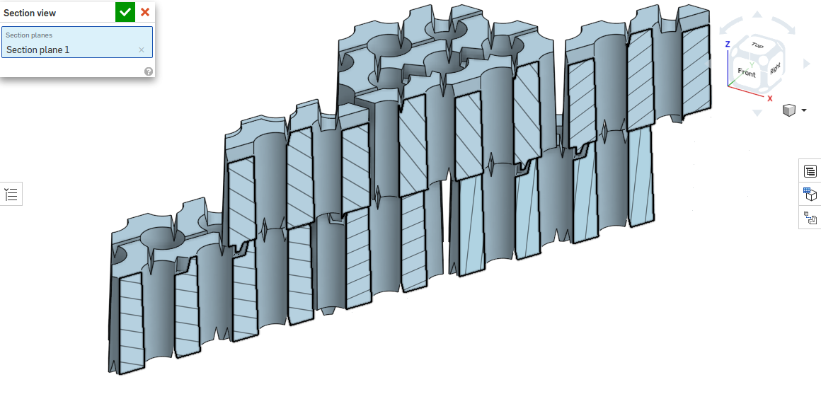
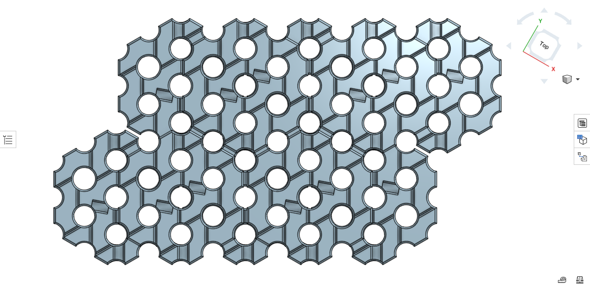
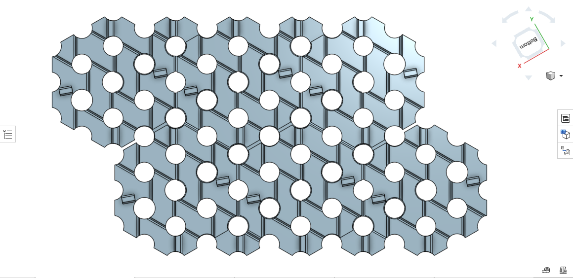
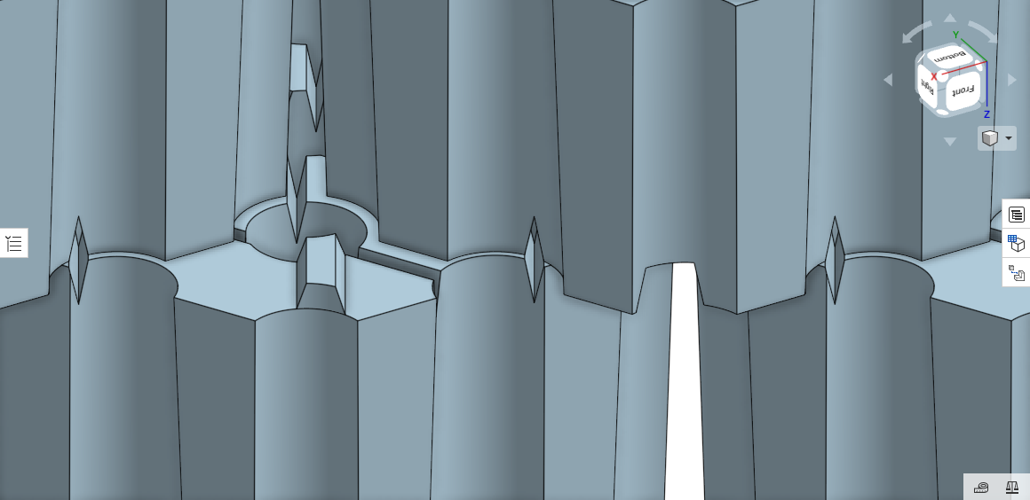
Along with the drawings of the chequer bricks are also presented views of the chequer bricks and the structure in the 3D version made in the new technical solution.
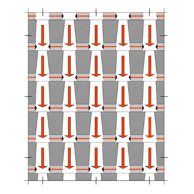
In order to minimize the possible increases of pressure in the vertical circulation of gases, a very small modification of the porosity of the new structure was used compared to the current one in this direction (below 5%). The joints of the new chequer brick in the structure are of the type "1 over 4 and 4 over 1" and are oriented radially towards the center of the chequer bricks so as not to generate problems due to expansion.
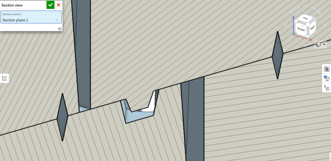
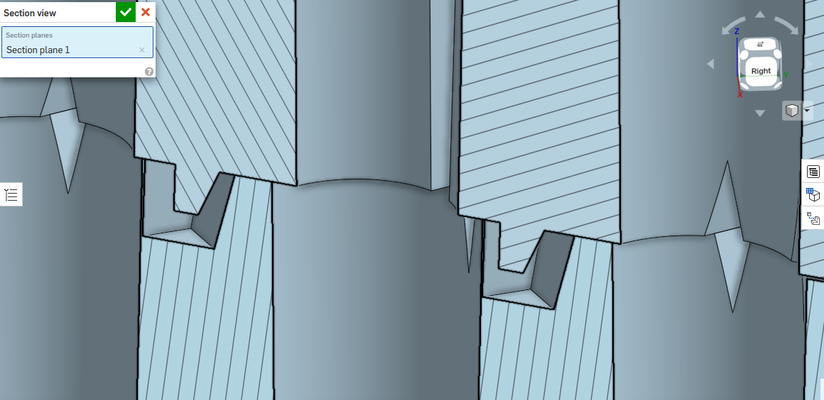
Due to the surface differences of the horizontal sections of the vertical channels that the internal horizontal channels join, the gas flow rate through the horizontal channels will be higher than that of the main vertical circulation, and due to the small sections of these horizontal channels the flow gas will have a laminar regime and not turbulent as in the case of vertical circulation.
When mounting the chequer bricks, most of the horizontal channels of the upper face overlap with the horizontal channels of the lower face in the next row, which makes the bearing surface to be maximum. In operation, due to expansion, this overlap decreases. The table shows the extreme (hypothetical) value in which the offset is total. This situation is to the advantage of the heat transfer surface, which will in reality, during operation, have a higher value than the one shown in the table, corresponding to the hypothetical situation.
It is observed that the manufacturing problems of the new type of chequer bricks compared to the existing one are not important, because the realization of these horizontal channels on the chequer brick surfaces is easily obtained by profiling triangular ribs on the pressing plates of the molds. It is understandable that sharp-edged edges will need to be replaced with curved connections and suitable radii.
Chequer brick assembly - new structure
Another example
Comparative table - example of chequer brick according to the patent
- dimensions at manufacture according to the drawings -
| Chequer brick type | Volume | Leaning surface | Thermal transfer surface |
| Existent (h=150mm) | 0,646 mc/mc | 0,448 mp/mc | 35,235 mp/mc |
| New (h=150mm) | 0,647 mc/mc | 0,494 mp/mc | 49 mp/mc |
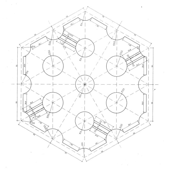
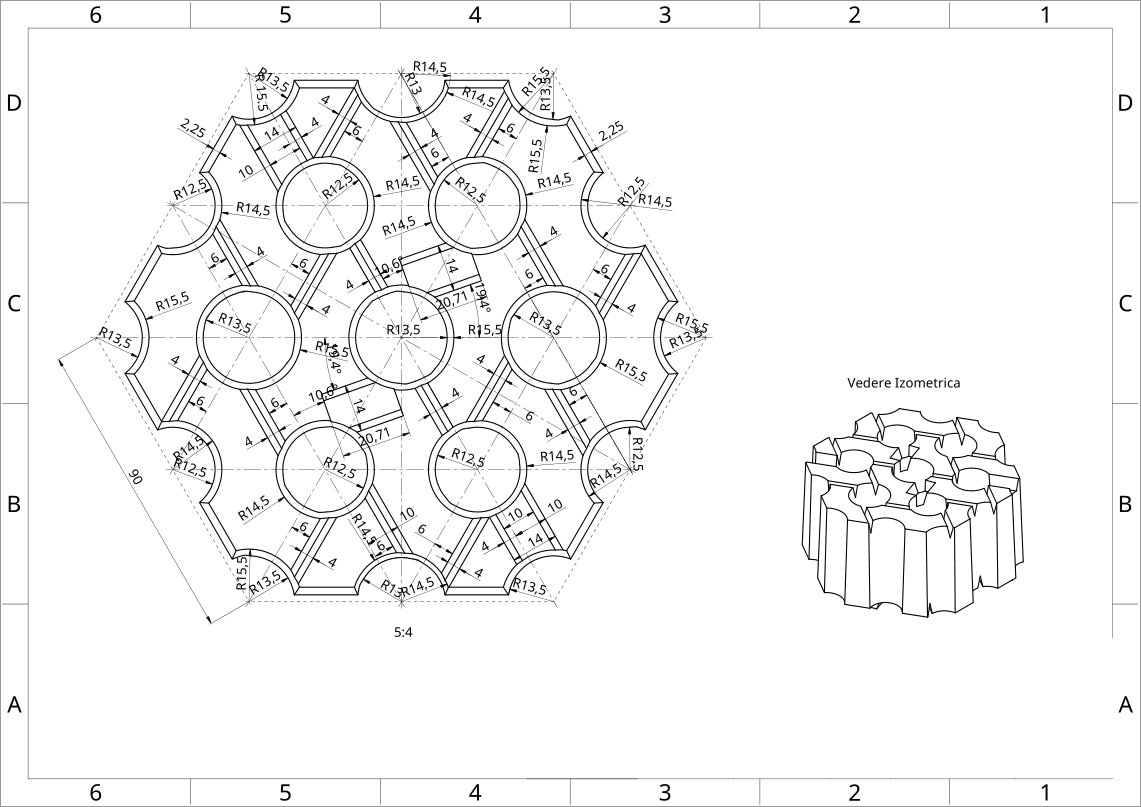
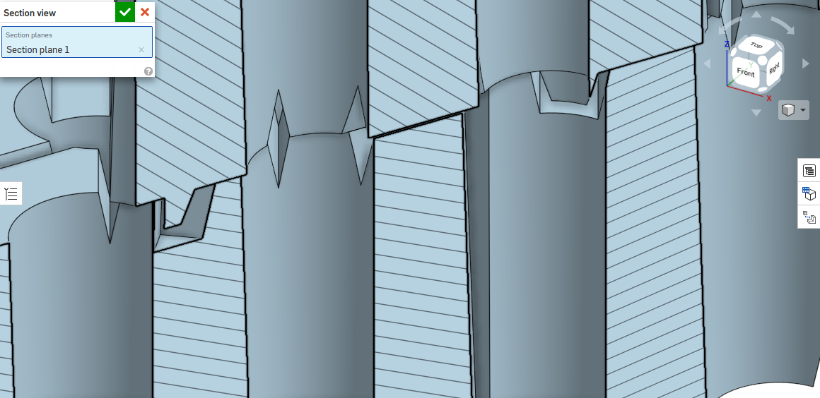
Horizontal circulation and turbulence
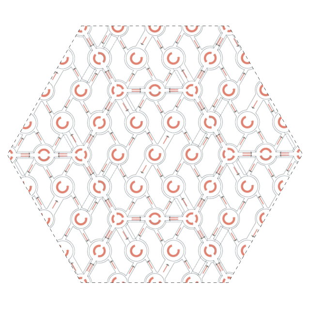
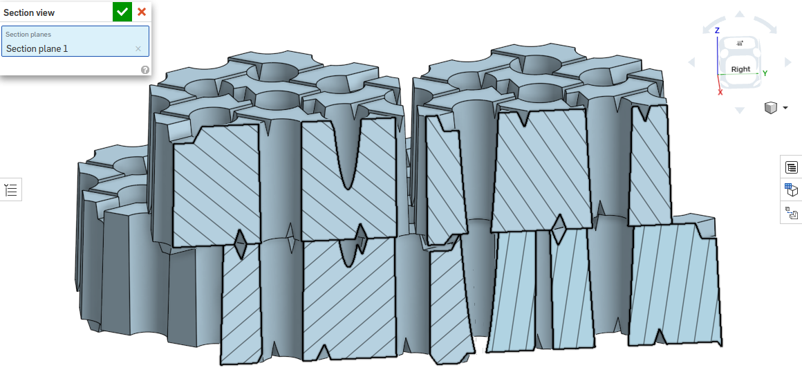
Horizontal and vertical circulation
Note:
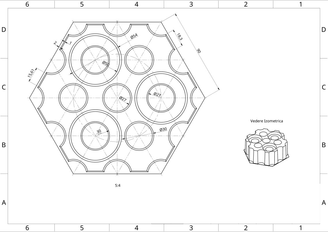
The example shows a type of silica chequer brick at the top of the regenerator at which the interaxial distance between the vertical channels is 55 mm, the height of the chequer brick is 150 mm and their average diameter is 32 mm. The horizontal channels in the new model are present only on the lower face of the chequer brick. Dimensions and calculations were made on the chequer brick from the manufacturing stage.
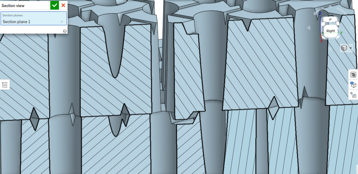
There are also presented two schematic figures of the appearance of horizontal vortices that the horizontal channels cause in the vertical flow of the main vertical channels as well as the alternating direction in which the gases enter and exit horizontally from one row to another in the structure of the vertical channels. This is happening because these channels are made up in height of gaps of alternately different sizes.
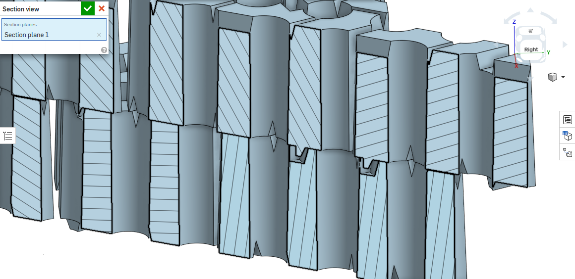
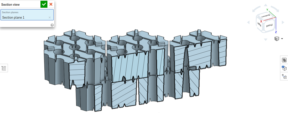
Old classical chequer brick vertical section
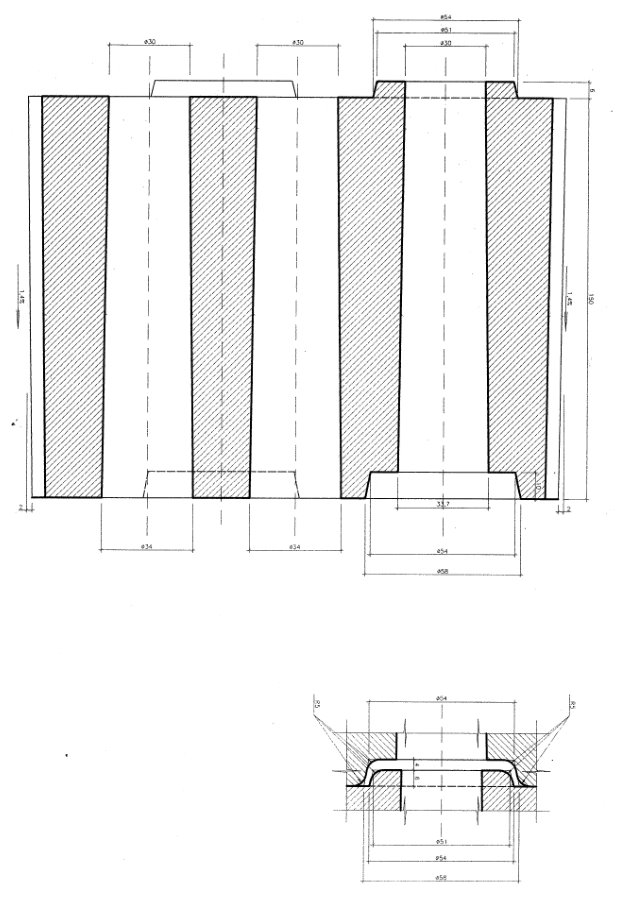
New chequer brick